Your one source for automation and information services

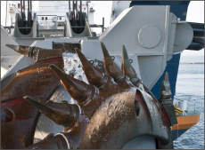
Electric Dredge
Kruse Controls, Inc. was contracted to automate many of the features found on a cutter/suction dredge. The customer’s goals for a new 100 foot sand and gravel dredge were to improve production efficiency, reduce downtime and automatically create daily reports detailing production, depths and locations dredged.
In order to meet the customer’s goals, the shore powered electric dredge was equipped with a PLC (Programmable Logic Controller), several VFD’s (Variable Frequency Drives), one computer for use as an operator interface and one computer for dredge position/depth control and logging.
The dredge has a 750KVA on-board transformer, which develops the 480VAC power necessary for the dredge’s forward and aft winches and ladder motors. Each motor is equipped with a VFD to allow speed and torque control for swinging the dredge or raising and lowering the ladder.
The PLC is the “on-board industrial computer” which controls the entire dredge. Through it’s input and output modules, it is connected to all of the field devices and VFDs which allows the PLC to monitor and control the dredge operation based on the operator entered parameters. Field devices typically found on manually controlled dredges, such as pressure transmitters, nuclear density meter, flow meter, inclinometer and linear displacement sensors are monitored by the PLC program to allow quick and automatic response to adverse conditions without operator intervention.
This dredge is equipped with a graphical touch screen, rather than levers, pushbuttons, switches and foot pedals, which is attached to the operator interface computer. This computer communicates with the PLC. The operator interface displays all of the dredge information including operational status, speeds, GPM, TPH, water pressure, oil pressure, ladder depth, discharge pressure, suction relief valve position, motor torques and suction vacuum. Additionally, all fault conditions and alarms are immediately displayed and annunciated on the operator interface screen, and then archived on the computer with a time and date stamp.
The dredge operator can navigate the dredge and operate its components manually via the touch screen, or he can enter automatic settings for production rate, suction vacuum and ladder depth, which allow the PLC program to control and optimize the process.
When in the fully automatic mode, the dredge swing speed, cutter speed and suction pump speed are controlled by the PLC program to maintain the operator specified TPH (Tons Per Hour) setpoint. The PLC program through automatic suction relief valve positioning maintains the suction vacuum.
Semi-automatic mode allows operator control of the swing speed. While swing speed is controlled in the operator-selected direction, motor torque is controlled for the opposite swing winch to maintain a taught cable and eliminate dredge walking from the cutter.
Regardless of the operating mode, conditions are continuously monitored by the PLC to automatically switch the controls back to manual mode under certain conditions. In critical situations, the swing winches are stopped. A separate screen on the operator interface computer displays historical trends of Tons per Hour, discharge pressure, oil pressure and other critical parameters.
A second on-board computer allows the dredge operator to visually monitor the dredge location and ladder depth in reference to the customer’s surveyed boundary lines. This computer runs an application of HyPack Max/DredgePack(tm) software for dredge depth and location logging and reporting. A GPS system interfaces with the DredgePack to allow coordinates, speed, location and heading to be displayed and logged on the computer. A scaled symbol of the dredge is super-imposed in real-time on the screen. The color graphical depiction of dredging locations and depths are printed daily for the customer’s records. If necessary, with the press of a computer key, the dredge operator can drop a virtual buoy on the screen to indicate trouble spots in the pond or to relocate to the same spot in the future. A customized software communication driver was developed to allow the DredgePack software and the PLC to share dredge ladder depth, draft and tide corrections, and other parameters. This allows for automatic control of the ladder depth and dredge location as required to satisfy permit constraints or topographical model tracking.
Not only were the customer’s goals achieved, but also the automation provided has been shown to a number of others, including two dredge manufacturers. The next phase will be to add an on-shore booster pump station to the PLC control system, using radio-telemetry to bring the data back to the main PLC.
As published from World Dredging Magazine, May 2001

Automation
Manufacturing IT

Security

Maintenance & Support
Dredge Automation