Your one source for automation and information services

Automation on the New Pheonix Pinelands Cutter Suction Dredge
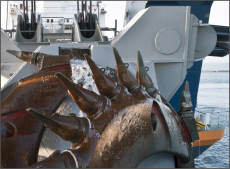
Kruse Integration was contracted to automate a DredgeMasters International, Inc. hydraulic cutter suction (CS) dredge. The customer was interested in automating the new dredge to produce efficiently, logically and automatically with little operator intervention.
The dredge is an 18-in. CS dredge with a 105-ft ladder capable of digging to 90 ft in the customer’s sand pit.
The dredge automation included automatic production control, automatic swing speed control, automatic swing direction control, automatic line plug detection and corrective action logic, automatic step forward logic, automatic wall detection and corrective action logic, auto-matic back-up logic, alarms, interlocks, trends of pressures, temperatures and production, remote shore control, DGPS logging and control as well as automatic ladder descent logic (detailed later).
Additionally, the automation will keep track of equipment usage and produce automatic daily reports of tonnage, alarms, operator selections, downtime and cutter depth with locations.
The integrated automation system includes an Allen Bradley PLC (programmable logic controller), an on-board industrial computer workstation with the graphical operator interface software, a duplicate graphical operator interface workstation for the remote office, an on-board industrial computer work station with DGPS software, an industrial uninterruptible power supply for the PLC and workstations, two DGPS receivers and antennas for dredge heading and cutter location, hydraulic valve control interface modules and wireless ethernet modems for dredge-to-office computer networking.
Additionally, this system includes all necessary hydraulic pressure transmitters, mag flow meter, densitometer, ladder inclinometer, level probes, discharge and vacuum pressures, fuel flow transmitters, voltage monitor transmitter, oil pressure transmitters and temperature transmitters to feed information to the PLC.
On Board PLC System
The PLC and supporting components are off-the-shelf common industrial controls devices found every day in the industrial field. There are no levers or knobs found on this dredge. All automatic and manual settings are operated through the workstation’s touch screen or the hand-held gamepad controller.
Main Status Screen
The on-board graphical operator interface allows the operator to enter operating parameters, limits, settings and automation selections. Additionally, descriptive text alarming, individual alarm defeat selectors, historical trend charts, touch screen slider controls for setting cutter speed, ladder speed, flow velocity, manual swing speed, stern winch speeds, swing winch mooring tensions and manual engine speed features are incorporated into the operator interface.
A hand-held gamepad controller was included to allow manual winch operation as an alternative to the touch screen. This has proven to be a creative feature while setting anchors.
Gamepad Controller Help Screen
The dredge has a DGPS (Differential Global Positioning System) integrated on board. This system uses two antennas and DGPS receivers interfaced to a standard computer workstation running DREDGEPACK ™ software.
The DredgePack software indicates the heading and location of the dredge and cutter superimposed on the coordinates of the customer’s sand mine. The actual cutter depth and location is indicated and logged every 5.0 ft as it moves about the pond by plotting representative colors of depth on the screen.
The DredgePack program communicates to the PLC through the on-board ethernet network. This is necessary to allow the PLC to share depth and cutter offset information with the DredgePack program, as well as allowing DredgePack to send heading and location information to the PLC.
Kruse Integration developed the required software interface driver to communicate with the main pump engine’s electronic status and diagnostics interface system. All of the Engine’s vital information is dis-played, monitored and trended on the graphical operator interface workstation.
Pump Engine Screen (Similar to the Aux. Engine Screen)
The patented PLC programming code is the heart of the automation system. The code was developed through years of experience on board CS dredges. It is a compilation of many of the best dredging operators, dredging engineers and the staff at Kruse Integration
The operator controls the ladder and cutter manually with the buttons and a speed control slider on the graphical operator interface workstation. Using the touch screen buttons or the gamepad controller, the operator can run or jog the ladder in either direction. The ladder jog buttons do not use the slider speed setting as do the RAISE and LOWER run controls. The jog feature is meant to be a fine tuning of the cut depth and should therefore be controlled at a slower speed. The jog speed can be adjusted by an operator entry value on the graphical operator interface workstation maintenance screen.
The PLC program has ladder operation interlocks built in. The Ladder will automatically stop when rising if it gets to the preset minimum cutter depth or hits the ladder upper limit switch. There is a float switch located on front of the dredge. It will detect if the front of the dredge is pulled down by the ladder being stuck when rising. The float switch will disable the ladder up motion. The Ladder will automatically stop while lowering if it reaches the preset maximum cutter depth. Additionally, the ladder is programmed to be disabled if the aux. engine isn’t running, DC power supply fails or the E-Stop button is pressed.
The forward and stern winches can be manually operated with the buttons and a speed control slider on the graphical operator interface workstation winches screen. The winch payout and pull in speeds are set by a single slider control. The slider will control the payout and pull in speed from 0 to 100%. The setting of the forward winch’s slider is ignored during swing mode (detailed later). When operating the forward winches from the graphical operator interface workstation winches screen, the swing control is disabled. This manual operation is for setting the anchor, installing cable, testing the winch or for maintenance purposes. If a winch is running in the manual mode, all graphical operator interface workstation screens will indicate, in red, that the operator has a winch running in manual mode. The winches can be jogged from the graphical operator interface workstation or via the hand-held gamepad controller.
Winches Manual Control Screen
Each of the winches has an Operator Entry setting for pressure limit and Pressure Alarm found on the maintenance screen. The winch hydraulic pressure can be limited through the PLC program. Although the hydraulic system has physical limiting orifices, it is possible to limit the hydraulic pressure to the winch via the pressure limit operator entry on the maintenance screen.
As the indicated pressure approaches the set limit, the PLC output is limited regardless of the Winch Slider Speed Control setting. If the hydraulic pressure exceeds the alarm setting, an audible alarm will sound and the appropriate fault text will display on all of the alarm banners found on any of the screens.
Maintenance and Alarm Limit Settings Screen
The swing system can be operated in manual or automatic mode by the Swing Mode Selector found on the graphical operator interface workstation main status screen. If the Swing Mode is in manual, the swing direction is controlled by the dredge operator. Touching the Swing Port button on the main status screen will swing the dredge in the port direction.
Touching the Swing Starboard button on the main status screen will swing the dredge in the starboard direction. An animated arrow will flash green on the button in the direction of the swing. The swing direction can also be controlled via the hand-held controller.
If Automatic Swing Mode is selected, the dredge will automatically reverse direction upon reaching the operator preset headings. While in the Automatic Swing Mode it is still possible to use the Swing Direction buttons.
The swing speed can be operated manually or automatically. If the swing speed is in manual, the speed is determined by the Operator Swing Speed Slider on the main status screen. If the swing speed is in automatic, the speed is determined by the PLC program based on the operator entered TPH (tons per hour) setting. As the actual TPH production (determined by the on board fllow and density meter) drops below the operator TPH setting, the swing speed will increase to improve production.
As the TPH production increases above the operator TPH setting, the swing speed will reduce, even stop, to maintain production settings. When swinging, the opposing swing winch will be in the Mooring Mode, allowing it to payout or pull in as needed to maintain the operator preset tension.
Because the cutter rotates forward in the port direction, the PLC program monitors the hydraulic pressure of the forward port swing winch while swinging in the port direction.
If the pressure is below normal operating parameters, the program assumes the cutter is walking the dredge in the port direction and automatically increases the mooring tension on the starboard winch.
Each graphical operator interface screen has an Emergency Backup button in the top left corner. When pressed, the outer stern winch brakes are automatically released, the forward winches are automatically set in the Mooring Mode and the center stern winch hauls in at the operator speed setting. This feature can be used to quickly back the dredge from a hazardous situation when necessary.
Auto Logic Screen
The PLC program incorporates an automatic feature to step the dredge forward following a sweep determining low production. Once the TPH production drops below the operator entered preset for an entire sweep, the dredge will automatically step forward a preset distance and continue to swing the same arc and depth in the new location. This automation feature is selectable as an option to the Automatic Ladder Descent feature, which lowers the cutter a preset distance following low production recognition.
The PLC logic monitors the system to determine if the pipe line is in danger of plugging. If the parameters are beyond the preset values, the dredge pauses swinging and the ladder rises several feet until the plug is cleared at which time the ladder will automatically descend to the original depth and continue swinging.
If the original depth is not achieved due to sloughing of material, the ladder will automatically settle at the new depth and continue to descend in the swing corner.
There is programming logic built in to determine if the ladder angle isn’t changing while it is rising. This scenario will assume that the ladder is stuck and therefore cease to raise the ladder while sounding an alarm.
Additionally, there is a Tilt Float switch located on the bow of the dredge to determine if the bow is being pulled under. Upon activation, the Automatic Ladder Raise is disabled.
A duplicate graphical operator interface workstation exists in the shore offices. This workstation is networked to the dredge graphical operator interface workstation through a set of wireless ethernet modems. The office workstation is used to monitor, or run the dredge remotely.
Additionally, it is used to collect production data for automatic daily report print-out reports of production, down-time, efficiency, depths, locations and operator entry changes.
(Article reprinted with permission of WORLD DREDGING Mining & Construction, May 2003)

Automation
Manufacturing IT

Security

Maintenance & Support
Dredge Automation